MOUND SEPTIC SYSTEMS
MOUND SEPTIC SYSTEMS
I have designed over 700 mound systems in Indiana. Contact me to find out how I can help you.
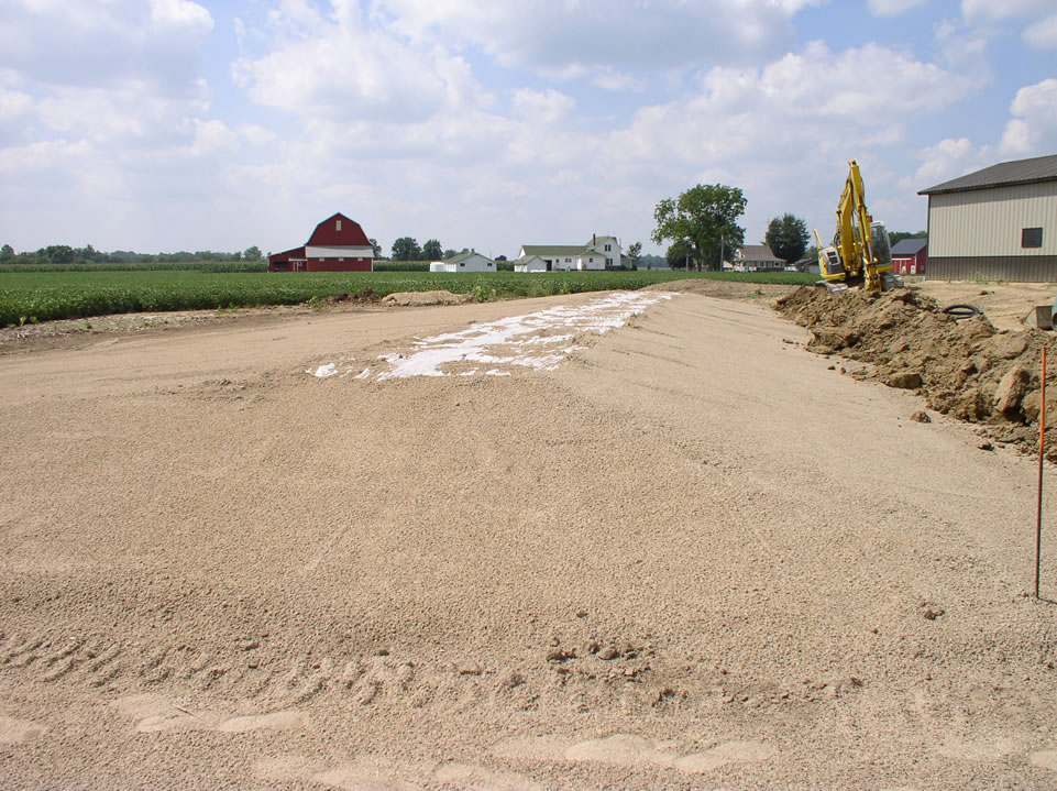
Side View of Mound Before Soil Cover – See Gravel Bed
Up-slope view of dual 230′ long mound systems
The above mound system is ready to be covered with soil. It was designed by Meade Septic Design Inc. and is being installed by Quality Excavating of Goshen. The machine to the right is installing a Perimeter Drain.
Click the image for more mound pictures.
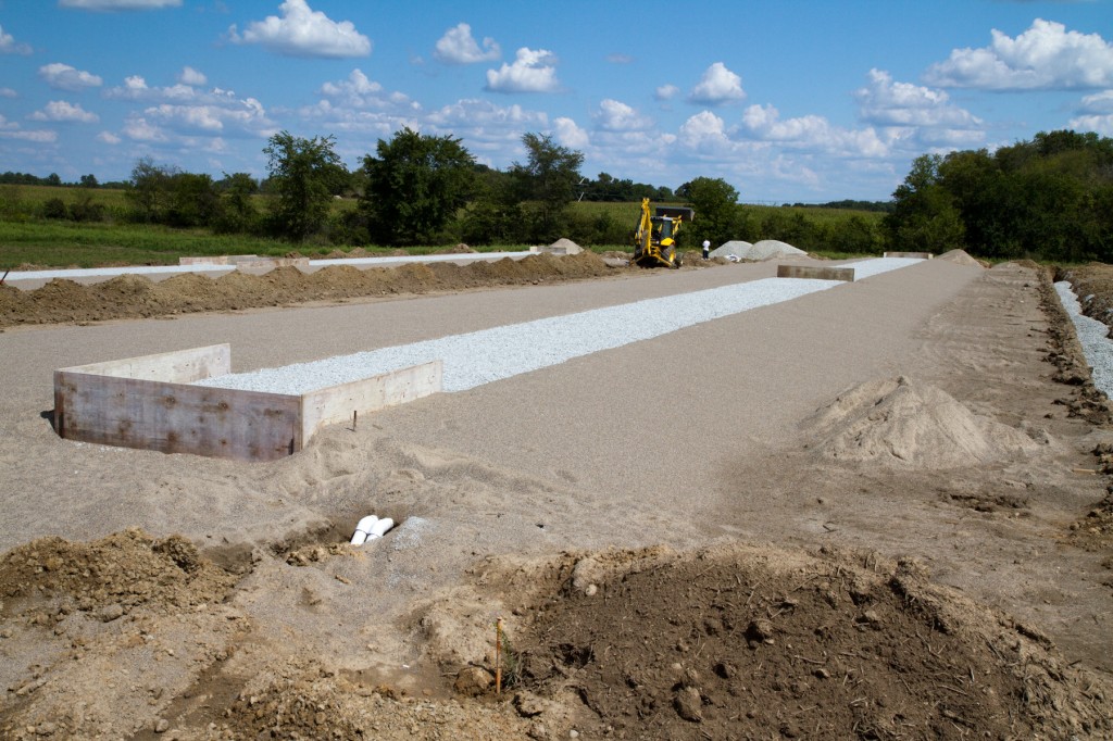
250′ Long Commercial Mound Designed by Meade Septic Design
Septic systems are usually composed of two main components: the septic tank, and the absorption field. Some systems, like mound systems, require a third component called a dosing tank or pump tank.
1. The septic tank is where raw wastewater goes initially. Two important things happen in the septic tank. First – the waste is partially treated and broken down by the anaerobic bacteria in the tank. Second – The waste settles into three layers: The sludge, the liquid effluent, and the scum layer (makes you hungry doesn’t it). A Baffle on the tank outlet allows only the liquid effluent (partially treated liquid sewage) to exit the septic tank and go to the absorption field, trapping everything else in the septic tank.
See our Septic System Care Page .
2. The Absorption field is where the liquid effluent infiltrates the ground. A mound system is a type of absorption field, so are trenches, beds, trench chambers, and drip irrigation.
3. The Dosing tank has a pump in it that is used to pump the liquid effluent to the absorption field. Effluent from the septic tank enters the dosing tank and at a specific height and turns on the pump by lifting the pump “on”float switch. Once on, the pump sends effluent through the force main (also called the delivery line) to the mound’s manifold which distributes the effluent to the small diameter laterals placed inside the gravel bed.
The carefully designed volume and rate of this dose pressurizes the distribution system so that the effluent is sprayed out of the lateral’s ¼” holes at a design head of three feet. The sprayed effluent is baffled (slowed) by the gravel in the bed and soaks down through the medium textured sand and is incorporated into the native soil below. The design must figure the size of the dose to be at least 7 times the volume of the laterals. Neglecting to properly design the dosing volume (that includes drainback to the tank) will mean that your distribution network fails to pressurize correctly.
The floats in the dosing tank are set to pump about four times a day (1/4 of the homes wastewater flow). All pump systems are (or at least should be) set up with a high water alarm. In the event that the pump should fail, the water level in the tank will continue to rise until it trips the high water alarm – letting you know that you have a problem in the dosing tank and that your afternoon is ruined.
The below dosing tank is equipped with a Sim Tech Filter which stops lint, hair and other debris from getting pumped out into the distribution network where it can plug the 1/4″ holes in the pressure distribution laterals. Meade Septic Design, Inc. recommends a Sim Tech Filter on all systems that utilizes pressure distribution. Spend 5 minutes watching the demonstration video and you will also be convinced.

Dosing Tank with Sim-Tech Effluent Filter

Commercial Dosing Tank and Controller

Aero-Tech ATUs (aerobic treatment units)
Learn more about Aerobic Treatment at Meade Septic Supply.com
The best way to learn about a mound system is to review how one is constructed. The following is a general description. Your local septic code may be different. Contact your local Health Department for details – Here we go!!
The area of the mound system is determined by the soil loading rate (how many gallons of effluent water per square foot per day the soil can absorb). Heavier soils have lower loading rates and therefore require larger absorption fields. The absorption area for a mound system is referred to as the Basal Area. The actual size of this area will vary. In Indiana, a typical mound system for a 3 bedroom house in clay soils can be expected to be about 95 feet x 32 feet. Preferably long and narrow, the mound must be designed parallel with the contour. Usually, the maximum allowed slope for a mound system is 6%.
- Force main: The force main connects the mound’s manifold (and laterals) to the pump in the dosing tank. The force main is usually installed between the mound and the dosing tank before any other part of the mound is constructed. The force main must be installed in a way that allows all the water in this pipe drain back to the dosing tank between doses or be installed at the frost layer to prevent freezing. Special care must be taken in choosing the size of the force main to ensure that it has a velocity of at least 2.0 feet per second.
- After determining the proper site for the system, the area is plowed .
- The plowed area is then coveredwith a one-foot-deep layer of washed medium textured sand (specification 23 sand in Indiana). This sand does a number of things.
- Supports the gravel bed
- Works as a single pass sand filter to partially clean the effluent as is passes through the sand
- Helps to distribute the liquid effluent throughout the absorption area and into the topsoil
- Next, a gravel bedis installed on top of the sand area. The size of the gravel bed is determined by the loading rate of the underlying medium sand. The bed is much smaller than the basal area and might be 75 feet long x 5 feet wide. Don’t be confused by the terminology, this is not a good place to spend the night!
-
- Distribution laterals are placed in the gravel bed (perhaps they are sleepy?). Laterals are laid parallel along the long axis of the bed about 3 feet apart. Laterals are usually 1″ – 1 ½” in diameter and made of PVC. ¼” holes are drilled on the bottom side of each lateral every three feet. The laterals are then manifolded together and the ends are capped.
- The gravel bed is then covered with a geotextile fabric (a coffee filter like fabric).
- The entire mound is covered with a 12″ of a loamy textured soil with heavier soil being around toe slopes of the mound.
- A thorough grass cover should be established on the mound. Don’t plant trees or shrubs on the mound, however, because their roots can cause problems.

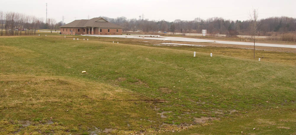
The sides of this mound are too steep (not designed by Meade)
General Tips on Mound Design:
-

Most septic systems fail over time because of a bio-mat build-up in the absorption field. A bio-mat in a mound system will usually form under the gravel bed between the sand and gravel. Water, now unable to move down through the sand, saturates the bed and begins to surface on top of the bed. Bio-mats can be prevented by utilizing an Aero-Tech aerobic treatment unit. My joint venture Meade Septic Supply LLC is the exclusive distributor for Aero-Tech ATUs in Indiana and Michigan. See my Meade Septic Supply LLC website for more details.
Be sure that your proposed mound system is designed by a professional with lots of experience. Incorrectly designed mounds can lead to various types of premature failure. Don’t assume that the local excavator (the one that gave you the lowest bid) is equipped to properly design the mound, they probably aren’t. Also, don’t assume that your local health department has the training or knowledge to perform a thorough mound system plan review. A mound system is a significant investment, and the design is the cornerstone of its construction. Don’t try to save money by shortcutting this important step.
Be sure that your pump is appropriate for the job. Effluent and Sewage pumps are made specifically for these types of applications and should last many years (see pump curves page) . A scouring velocity of at least 2.0 ft/sec. must be achieved in all piping! Don’t let someone sneak you a regular basement sump pump. Sump pumps are for occasionally pumping of clear water out of your basement and not for septic systems! They aren’t designed for the consistent demands — or the caustic environment — of a dosing tank.
Delivery Lines (also known as force mains) must be designed to drain back to the dosing tank unless they are buried at the frost layer and designed to remain full between doses. Incorrect design or installation of the delivery line could mean freezing and big problems… not something you want to deal with on the coldest day of the year!
More about Meade Septic Design Inc. Services
View Meade Septic Design, Inc. Commercial Clients and Projects
Got septic system questions? Email me.